CNC Shield V3 engraving machine 3D Printer+ 4pcs A4988/DRV8825/AT2100 Driver expansion board for Arduino + UNO R3 with USB cable
Regular price
Rs.20,511.16
Shipping calculated at checkout.
Stay up to date with order notifications
QUESTIONS & ANSWERS
Have a Question?
Be the first to ask a question about this.
Share this Product

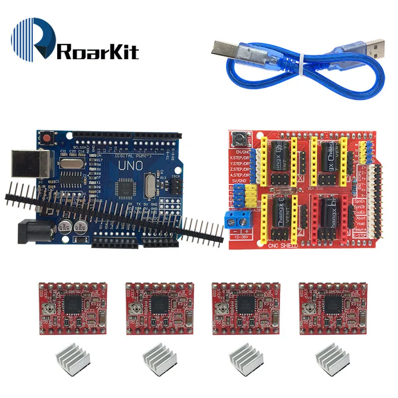
Shipping list:
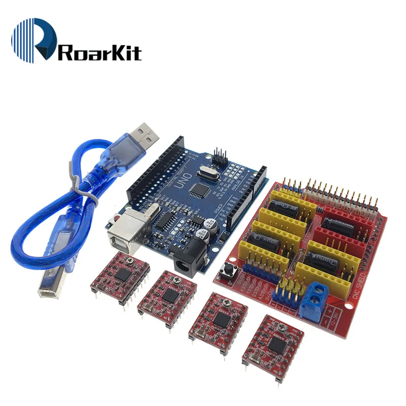
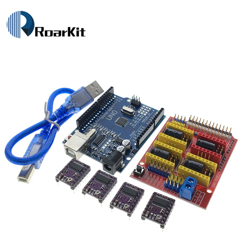
1 X CNC Shield V3
4 X A4988 Green / Red / DRV8825 / AT2100
4 X Heatsink
1 X UNO R3
1 X USB cable
A4988 Brief introduction:
One, Introduction
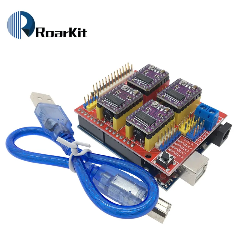
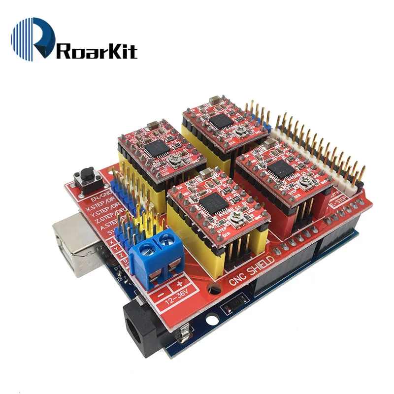
This expansion board as a driver expansion board, can be used for engraving machines, 3D printers.
It is a total of four slots, can drive four A4988 stepper motor. Each road stepper motors only need two IO ports. In other words, six IO ports can be well managed three stepper motors. Very convenient to use.
Two, UNO module IO port correspondence introduction.
IO corresponding figure above
UNO --------------------- expansion board
8 ------------------------ EN ( stepper motor driver enable , active low )
7 ----------------------- Z.DIR (Z -axis direction control )
6 ----------------------- Y.DIR (Y -axis direction control )
5 ----------------------- X.DIR (X -axis direction control )
4 ---------------------- Z.STEP (Z -axis stepper control )
3 ---------------------- Y.STEP (Y -axis stepper control )
2 ---------------------- X.STEP (X -axis stepper control )
/ / The following is a simple stepper motor control procedures,
# define EN 8 / / stepper motor enable , active low
# define X_DIR 5 / / X -axis stepper motor direction control
# define Y_DIR 6 / / y -axis stepper motor direction control
# define Z_DIR 7 / / z axis stepper motor direction control
# define X_STP 2 / / x -axis stepper control
# define Y_STP 3 / / y -axis stepper control
# define Z_STP 4 / / z -axis stepper control
/ *
/ / Function : step . function: to control the direction of the stepper motor , the number of steps .
/ / Parameters : dir direction control , dirPin corresponding stepper motor DIR pin , stepperPin corresponding stepper motor " step " pin , Step number of step of no return value.
* /
void step (boolean dir, byte dirPin, byte stepperPin, int steps)
{
digitalWrite (dirPin, dir);
delay (50);
for (int i = 0; i <steps; i + +) {
digitalWrite (stepperPin, HIGH);
delayMicroseconds (800);
digitalWrite (stepperPin, LOW);
delayMicroseconds (800);
}
}
void setup () {/ / The stepper motor used in the IO pin is set to output
pinMode (X_DIR, OUTPUT); pinMode (X_STP, OUTPUT);
pinMode (Y_DIR, OUTPUT); pinMode (Y_STP, OUTPUT);
pinMode (Z_DIR, OUTPUT); pinMode (Z_STP, OUTPUT);
pinMode (EN, OUTPUT);
digitalWrite (EN, LOW);
}
void loop () {
step (false, X_DIR, X_STP, 200); / / X axis motor reverse 1 ring, the 200 step is a circle.
step (false, Y_DIR, Y_STP, 200); / / y axis motor reverse 1 ring, the 200 step is a circle.
step (false, Z_DIR, Z_STP, 200); / / z axis motor reverse 1 ring, the 200 step is a circle.
delay (1000);
step (true, X_DIR, X_STP, 200); / / X axis motor forward 1 laps, the 200 step is a circle.
step (true, Y_DIR, Y_STP, 200); / / y axis motor forward 1 laps, the 200 step is a circle.
step (true, Z_DIR, Z_STP, 200); / / z axis motor forward 1 laps, the 200 step is a circle.
delay (1000);
}
Note: When inserting the A4988 module, must be careful not to insert opposite. Stepper motor wiring as follows:
2A, 2B is a group (red, green), 1A, 1B is a group (blue, yellow), if want to change direction, can be change the position of one group , for example 2A, 2B mutually exchanged.
DRV8825 Brief introduction:
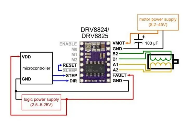
The DRV8825 stepper motor driver carrier board TI DRV8825 micro bipolar stepper motor drive is a breakthrough. The module has a pinout and interface with our A4988 stepper motor driver carrier is almost the same, so it can be used as a better performance of the pull-down menu board replacement in many applications. DRV8825 features an adjustable current limit, overcurrent and overtemperature protection, six micro-resolution (down 1/32-step). It uses 8.2 - 45 V, can provide up to about 1.5 per phase no heat sink or forced air flow (rated up to 2.2 per volume sufficient additional cooling).
Product Features
A simple steps and direction control interface
2 six different steps resolutions: full step, half step, 1/4-step1/8-step1/16-step, 1/32-step
3.CAN interface directly with 3.3 V and 5 V systems
4 Over-temperature thermal shutdown, overcurrent shutdown, undervoltage lockout
5 short to ground short circuit load protection
6.4 Layer 2 oz copper PCB, in order to improve heat dissipation
7 exposed solder ground below the bottom of the driver IC on the printed circuit board pad
8 module size, pin and interface matching A4988 stepper motor driver operators in many ways
9 adjustable current control lets you set a potentiometer, which lets you use the stepper motor's rated voltage or more, in order to achieve a higher rate of maximum output current step
10 Intelligent chopping control automatically selects the correct current decay mode (fast decay or slow decay)
11 Maximum 45 V supply voltage
12 built-in voltage regulator (the need for any external logic supply voltage)







![[variant_title] - CNC Shield V3 engraving machine 3D Printer+ 4pcs A4988/DRV8825/AT2100 Driver expansion board for Arduino + UNO R3 with USB cable](http://smartdevice.pk/cdn/shop/products/HTB1rtkRayzxK1Rjy1zkq6yHrVXa2_{width}x.jpg?v=1569823999)
![[variant_title] - CNC Shield V3 engraving machine 3D Printer+ 4pcs A4988/DRV8825/AT2100 Driver expansion board for Arduino + UNO R3 with USB cable](http://smartdevice.pk/cdn/shop/products/HTB1OtcYavfsK1RjSszgq6yXzpXa5_{width}x.jpg?v=1569823999)
![[variant_title] - CNC Shield V3 engraving machine 3D Printer+ 4pcs A4988/DRV8825/AT2100 Driver expansion board for Arduino + UNO R3 with USB cable](http://smartdevice.pk/cdn/shop/products/HTB1Pc.QavfsK1RjSszbq6AqBXXaQ_{width}x.jpg?v=1569823999)
![[variant_title] - CNC Shield V3 engraving machine 3D Printer+ 4pcs A4988/DRV8825/AT2100 Driver expansion board for Arduino + UNO R3 with USB cable](http://smartdevice.pk/cdn/shop/products/HTB1ugp.azLuK1Rjy0Fhq6xpdFXaW_{width}x.jpg?v=1569823999)
![[variant_title] - CNC Shield V3 engraving machine 3D Printer+ 4pcs A4988/DRV8825/AT2100 Driver expansion board for Arduino + UNO R3 with USB cable](http://smartdevice.pk/cdn/shop/products/HTB1r1mOBkzoK1RjSZFlq6yi4VXaV_{width}x.jpg?v=1569823999)
![[variant_title] - CNC Shield V3 engraving machine 3D Printer+ 4pcs A4988/DRV8825/AT2100 Driver expansion board for Arduino + UNO R3 with USB cable](http://smartdevice.pk/cdn/shop/products/HTB1uloPasfrK1RkSmLyq6xGApXaN_{width}x.jpg?v=1569823999)


![[variant_title] - CNC Shield V3 engraving machine 3D Printer+ 4pcs A4988/DRV8825/AT2100 Driver expansion board for Arduino + UNO R3 with USB cable](http://smartdevice.pk/cdn/shop/products/HTB1rtkRayzxK1Rjy1zkq6yHrVXa2_grande.jpg?v=1569823999)
![[variant_title] - CNC Shield V3 engraving machine 3D Printer+ 4pcs A4988/DRV8825/AT2100 Driver expansion board for Arduino + UNO R3 with USB cable](http://smartdevice.pk/cdn/shop/products/HTB1OtcYavfsK1RjSszgq6yXzpXa5_grande.jpg?v=1569823999)
![[variant_title] - CNC Shield V3 engraving machine 3D Printer+ 4pcs A4988/DRV8825/AT2100 Driver expansion board for Arduino + UNO R3 with USB cable](http://smartdevice.pk/cdn/shop/products/HTB1Pc.QavfsK1RjSszbq6AqBXXaQ_grande.jpg?v=1569823999)
![[variant_title] - CNC Shield V3 engraving machine 3D Printer+ 4pcs A4988/DRV8825/AT2100 Driver expansion board for Arduino + UNO R3 with USB cable](http://smartdevice.pk/cdn/shop/products/HTB1ugp.azLuK1Rjy0Fhq6xpdFXaW_grande.jpg?v=1569823999)
![[variant_title] - CNC Shield V3 engraving machine 3D Printer+ 4pcs A4988/DRV8825/AT2100 Driver expansion board for Arduino + UNO R3 with USB cable](http://smartdevice.pk/cdn/shop/products/HTB1r1mOBkzoK1RjSZFlq6yi4VXaV_grande.jpg?v=1569823999)
![[variant_title] - CNC Shield V3 engraving machine 3D Printer+ 4pcs A4988/DRV8825/AT2100 Driver expansion board for Arduino + UNO R3 with USB cable](http://smartdevice.pk/cdn/shop/products/HTB1uloPasfrK1RkSmLyq6xGApXaN_grande.jpg?v=1569823999)


![[variant_title] - Proto Screw Shield V2/V3 Assembled prototype terminal expansion board for Arduino UNO R3](http://smartdevice.pk/cdn/shop/products/HTB1cMESbdfvK1RjSszhq6AcGFXaK_{width}x.jpg?v=1569827511)

![[variant_title] - Liquid PH Value Detection Regulator Sensor Module Monitoring Control Meter Tester + BNC PH Electrode Probe For Arduino](http://smartdevice.pk/cdn/shop/products/HTB1gm15Xkfb_uJkSmFPq6ArCFXab_{width}x.jpg?v=1569826063)